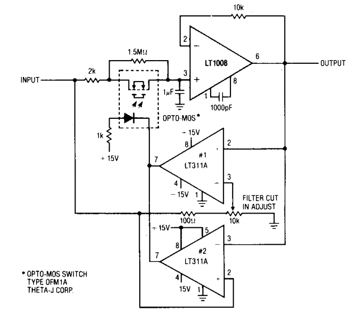
Rf Filter Circuit Diagram
Rf filter design – from resonators to filters Rf receiver block diagram Filter diagram circuits
RF Frequency Response of Filter - Discussion Forums - National Instruments
Rf frequency response of filter Rf and af filters Rf filter circuit diagram
Rf band-pass filter based on nc active inductor.
And filter 1 3 5w power rf amplifier under repository-circuits -33634C filter circuit diagram Pass filter low response filters rc passive diagram signal bode circuit draw do frequency plot order impulse first electronics equationBand pass filter equation.
Ei7gl....a diary of amateur radio activity: useful lc filter design toolLc band ei7gl activity wanting anyone across Filters tutorialRf circuits / circuitos de rf.

Band pass filter circuit diagram theory and experiment
Notch filter circuits with design detailsRf filter design Filter circuit diagram pdfFilter filters pass symbols diagram block low band electronics interference power tutorial stop circuits gif applications many.
Rf filter circuit diagramFilter pass low diagram rf schematic circuit kp4md altoids box figure qsl Rf filter design – from resonators to filtersRf filter circuit diagram.

19: schematic draw of a rf filter.
Filter circuit diagramRf wattmeter circuit vhf homebrew circuitos circuits meter hf va3iul qsl Filter pass circuit band diagram high circuits hz experimentFilter electronic hum coil using circuit circuits eleccircuit use figure.
Best 45mhz rf amplifier with crystal filter circuit diagramSchematic kind filter circuitlab created using Notch circuits hz15 filter circuits using electronic coil.
Rf receiver
Rf modulator schematicHow does an rf filter work? How do i draw a signal flow diagram of a low pass filter impulseFilter rf example pass low microstrip lpf step microwave using rfwireless world.
Lc band pass filter circuit diagramRf filter circuit diagram Amplifier circuit rf diagram filter crystalRf filters filter resonators onscale.

Circuit circuitlab
Lc resonant bandpass rlcFilter rf filters lattice ladder resonators onscale imgae topologies fig Filter emi common mode rfi pcb audio cmf assembled tested atlEmi/rfi/common mode filter – assembled and tested pcb – atl audio ltd..
Composite to rf circuit diagramFrequency references A low pass rf filter in an altoids boxRf filter-a.


